CHOOSING THE RIGHT 1-WIRE MASTER FOR EMBEDDED APPLICATIONS

This application note presents three categories of 1-Wire master circuits for embedded applications and discusses their capabilities and requirements in relation to available (i.e., unused) system resources. This application note presents three categories of 1-Wire master circuits for embedded applications and discusses their capabilities and requirements in relation to available (i.e., unused) system resources. Instructions and a decision matrix are included to identify the most effective 1-Wire master for the application. The reader should be familiar with the basics of 1-Wire communication and microcontrollers. Introduction The 1-Wire bus is a simple signaling scheme that performs half-duplex bidirectional communications between a master controller and one or more slaves sharing a common data line. Both power delivery and data communication take place over this single line, making 1-Wire devices unmatched in their ability to provide key functions to systems where interconnect must be minimized. The 1-Wire products provide combinations of memory, mixed-signal, and secure authentication functions through a single-contact serial interface. Typical applications of 1-Wire devices are: identification of print cartridges or medical consumables; calibration and control of rack cards; identification and authentication of printed circuit boards (PCBs), accessories, and peripherals; protection of intellectual property; clone prevention; and secure feature control. To take advantage of 1-Wire technology, one needs a 1-Wire master that generates the waveforms necessary to identify the devices on the bus and to communicate with them. There are numerous ways to construct a 1-Wire master. This application note discusses masters for embedded applications (i.e., short networks that have no more than three to five 1-Wire slaves). For designs using 1-Wire for long lines or with a larger number of slaves, see Maxim application note 148, "Guidelines for Reliable Long Line 1-Wire Networks." The 1-Wire masters described in this application note are compatible with host circuits that operate on a 3V to 5V supply. The circuits that do not involve protocol conversion can also be used with hosts that operate on a supply of less than 3V. In that case, a voltage-level translator between the master and 1Wire slaves is needed. Maxim application note 4477, "Reference Design of a 1-Wire Bidirectional Voltage Level Translator for 1.8V to 5V," presents such a circuit. R4 in application note 4477 corresponds to R in this application note. 1-Wire Glossary There are several terms commonly found in 1-Wire documents that should be explained at the outset. Host Interface The circuits discussed in this document are 1-Wire masters—they all communicate with 1-Wire slaves. These 1Wire masters, however, cannot function as standalone entities. They need a host microcontroller that tells them what to do on the 1-Wire side. Operating Voltage Typically, 1-Wire devices function over the following voltage ranges: ®
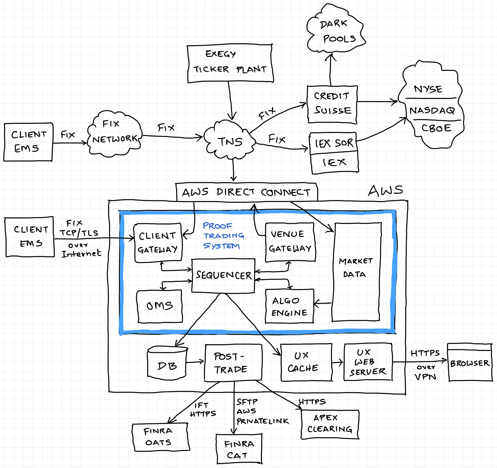
Proof Engineering: The Algorithmic Trading Platform, by Prerak Sanghvi, Proof Reading
Implementing an Isolated 1-Wire Bus

Experimental data and clock multiplexing technique for implementing single wire synchronous data Bus
DC1811A-KIT Reference Design, DC to DC Multi-Output Power Supplies
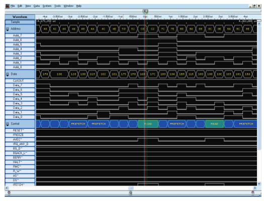
Debugging Serial Buses in Embedded System Designs

DS2401Z+T&R Application Note Maxim Integrated
DC1337A Reference Design, Analog to Digital Conversion

Choosing the Best Lifting Sling: Wire Rope vs. Chain. vs. Synthetics

LabJack T8-Isolated, Simultaneous, 24-bit Precision Analog Inputs
DC2420A-KIT Reference Design, Temperature Measurement
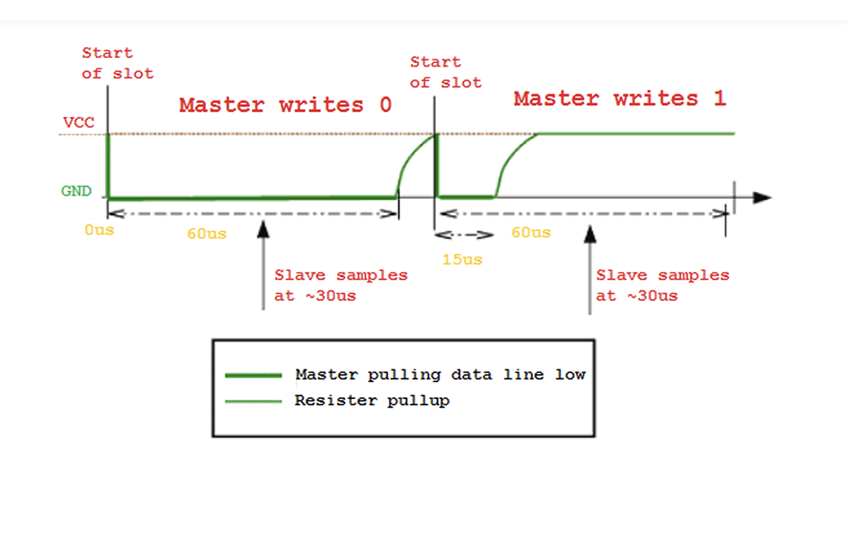
What is the 1-Wire protocol?